http://www.4wdmechanix.com/Tuning-and-Troubleshooting-the-2.5L-Jeep-TBI-Four?r=1Posted on Apr 22, 2015 at 1:44 am · by
Moses LudelHow-to: Tuning & Troubleshooting Jeep 2.5L TBI Four-Cylinder EnginesIn 1986, the AMC 2.5L/150 four cylinder engine gained throttle body injection in the XJ Cherokee applications. This same engine in the Jeep CJ models still used a carburetor. The YJ Wrangler application of the 2.5L, introduced with the 1987 models, came with TBI, making this feisty engine the first use of fuel injection in a Jeep utility 4×4 model.
TBI is a bona fide electronic fuel-and-spark management system. While not as efficient or power-producing as multi-point fuel injection, TBI has all the off-highway and high-altitude benefits of electronic fuel-and-spark management. Constant feedback from sensors, electronic fuel delivery and spark timing, the TBI system provided cleaner emissions and improved drivability both on- and off-highway.
The 2.5L four with TBI was only offered from 1986-90. To serve the needs of pre-MPI YJ 2.5L owners, this article focuses on the components and potential trouble spots of the TBI system. Diagnostics involve computer interrogation and trouble codes from the TBI system, much like the MPI engines that follow in the 1991 2.5L and 4.0L designs. TBI also serves as a good introduction to EFI design and concepts.
NoteAn orientation to basic TBI functions is useful for both TBI and MPI troubleshooting. Equipped with this knowledge, four-wheelers will have more confidence when leaving the paved highway for remote backcountry treks. This section provides Jeep owners with a basic understanding of electronic fuel injection.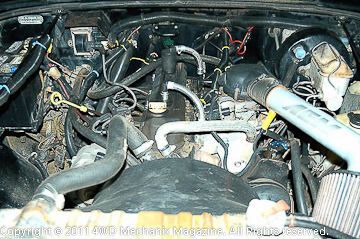 The 1987 YJ Wrangler (shown) offers the first TBI engine in a utility Jeep 4×4 model. TBI has all of the benefits of a true EFI system. Fully electronic fuel-and-spark management eliminates the mechanical/vacuum advance ignition and a feedback carburetor. In its place is an Electronic Control Unit (ECU) that relies upon a host of engine sensors to adjust the ignition timing and fuel pulse width/flow in milliseconds. TBI provides optimal compensation for altitude, vehicle angles and throttle demands.
 Right side engine view reveals a distributor, spark leads, a remote coil/ignition module (ICM) and the MAP sensor. The ignition system appears conventional. However, the ignition distributor no longer has mechanical or vacuum advance mechanisms. The distributor has no pickup, either. In this design, timing is controlled at the ECU computer. The ICM and coil send secondary (high) spark voltage to the distributor cap. The rotor distributes spark to each cylinder in the firing order: 1-3-4-2.
 Routine service and troubleshooting of the distributor consists of confirming that the shaft turns properly and the cap/rotor components are in good condition. Like a conventional ignition, TBI 2.5L maintenance steps consist of spark plugs, spark plug wires, the distributor cap and rotor. Check for cracks, wear and corrosion at the cap and rotor contacts. Test spark wires and the coil lead for ohms resistance. Troubles beyond this will point to the ICM/coil, ECU or faulty sensor signals.Setting Base Timing on the 2.5L TBI Four and the MPI Engines
While the ignition timing is fully controlled by the ECU and ICM systems, the distributor plays a critical role in delivering spark to each cylinder. For the TBI four and later MPI engines with a distributor, the distributor mounts in a fixed position and does nothing more than distribute spark to each of the cylinders in the firing order. The ECU computer or PCM knows the piston positions from the crankshaft position sensor (CPS) signal at the flywheel.
Setting fixed timing requires a one-time location of the distributor. On a TBI or MPI Wrangler engine, you cannot adjust spark timing by moving the distributor housing! Timing is a programmed function of the ECU or PCM computernot the distributor. 2.5L MPI and 4.0L MPI engines locate the rotor in a different position than the TBI distributor depicted in this section. (See Note below for MPI timing details.)
NoteOn 1991-up MPI engines, the 2.5L distributors rotor faces slightly past 3 oclock when aligned with #1 cylinders spark wire leadnot 6 oclock as with the 1986-90 2.5L TBI engines. Start the 2.5L MPI distributor with the oil pump tang near 10 oclock to place the rotor at slightly past 3 oclock with the distributor housing seated. On MPI 4.0L engines, align the oil pump tang near 11 oclock to place the distributor rotor at 5 oclock with the distributor housing seated. All settings reflect #1 piston at TDC on its compression stroke.To index or position the distributor properly, begin by making sure that #1 piston is rising on its compression stroke. Ignition OFF and coil wire detached for safety sake, you can remove the #1 spark plug if necessary to note the cylinder pressure as the piston rises on this stroke. Rotate the crankshaft with a hand wrench, bringing the damper mark just to the TDC (0-degree position) in the normal direction of rotation. In the steps shown here, I share the one-time, required setting of the distributor. You can use this procedure at your shop or in a field emergency.

Here, I have aligned the 0 degree mark with the crankshaft pulleys damper notch for TDC on #1 piston. (If necessary, remove the #1 spark plug and feel for pressure to confirm that the piston for #1 cylinder is reaching the top of its compression stroke and not the exhaust stroke.) As shown, the #1 piston is at the top of its firing stroke or top-dead-center (TDC).
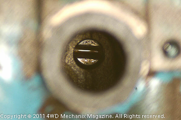 The distributor has an additional and very important role: driving the oil pump! At the base of the distributor shaft, there is a tang that fits into the slot at the top of the oil pump drive shaft. Since the camshafts drive gear and distributors driven gear are helically cut, the distributor shaft will turn as the distributor drops into position and engages the oil pump drive. For 2.5L TBI fours, the oil pump drive should be aligned at slightly past 3 oclock for the distributor to end up with the rotor facing 6 oclock. Install a new distributor housing-to-block base gasket or O-ring as required.
 If the oil pump drive and distributor tang align during fitment, the rotor will wind up facing 6 oclockcorrect for the 1987-90 2.5L TBI fours. If the rotor does not face 6 oclock as shown, the distributor must be lifted up and the oil pump drive realigned with a screwdriver. Try again, with the distributor tang engaging the pump drive slot near 3 oclock then rotating to place the rotor blade at 6 oclock with the distributor housing fully seated. Make certain the housing seats flush with the bolt slot aligned correctly. Torque the clamp bolt to 17 ft-lbs.NoteOn MPI 2.5L engines, the rotor blade should face slightly past 3 oclock when the distributor seats. An MPI 4.0Ls rotor blade should face 5 oclock with the distributor housing seated. This requires an oil pump drive alignment near 10 oclock for 2.5L MPI fours and near 11 oclock for 4.0L MPI sixes. When installed right, the rotor will face the correct clock position with the distributor housings bolt notch aligned with the engine block bolt hole. All references are with #1 piston at TDC on its compression stroke. Torque the clamp bolt to 17 ft-lbs.
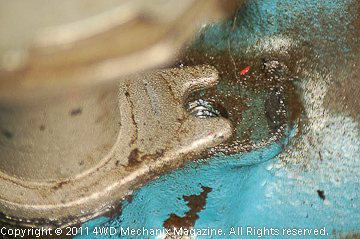 Here, the distributor housing locating tab is clearly in place. This distributor will only fit in one position. With #1 piston at TDC on its compression stroke, and with the rotor facing 6 oclock, you can secure the hold-down hardware to 17 ft-lbs torque. The spark plug wires will go in place, with #1 lead at the 5 oclock distributor cap position and the other three leads placed clockwise in the firing order: 1-3-4-2. The center tower of the distributor cap accepts the ICM/coil lead. Seat spark wires securely.NoteFor 2.5L and 2.4L engines, the cylinders number 1-2-3-4 from front to rear. 4.2L and 4.0L engines number 1-2-3-4-5-6 from front to rear.
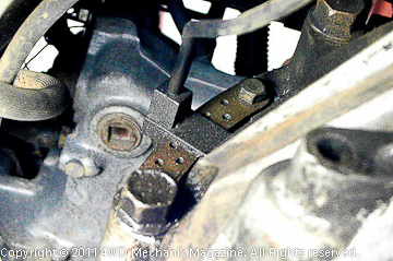 EFI/TBI systems depend upon a strong signal from the engine speed sensor. The sensor calculates TDC by reading a trigger tooth on the flywheel or flexplate. This Crankshaft Position Sensor (CPS) is common to 2.5L and 4.0L engines. Mounted at the left upper section of the flywheel/converter housing, the CPS is vulnerable to dust, dirt and oil. At high mileage, as oil accumulates on the flywheel or flexplate, the sensor may fault. Simply removing and cleaning the device can often restore performance and eliminate hard engine starts.
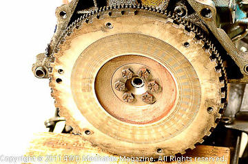 Flywheel or drive plate has notch teeth. The CPS has a magnetic probe that finds the gap in this set of teeth. 12 teeth later, a reference piston reaches TDC (top-dead-center). The ECU uses this reference and sensor input for firing mixtures and setting the ignition spark advance and retard. This is a highly accurate system that can adjust timing in milliseconds. Spark to plug wires reflects ever-changing ICM signals and coil triggers.NoteThe manual clutch flywheel or automatic transmission drive plate is somewhat inaccessible for cleaning. If the rear main seal leaks on a 2.5L or 4.0L engine with a CPS, fix the main seal leak to eliminate risk of chronic oil contamination of the speed sensor, which will produce hard starting and no starts. You can test the 2.5L TBI engines CPS across its A and B terminals with the engine hot, shut off and the connector loosened: Quick diagnostic readings should be 200 plus-or-minus 75 ohms.
 TBI electronic fuel-and-spark management uses an ignition control module (ICM) that interfaces with the ECU. Ignition spark advance and retard each rely upon a signal from the ECU to the ICM. The ICM output is simple enough, with just a tachometer lead and a high voltage spark wire lead from the coil to the distributor cap high tension tower (center post). Fortunately, if the coil is defective, this is an item that can be serviced separately and does not require replacement of the entire ICM.
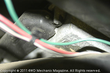 The ECU (electronic control unit) mounts above the heater assembly on this early YJ with 2.5L TBI. This ECU uses a 35-Pin type plug harness. The ECU controls spark output and timing once the distributor base timing is correct. Signals from the coolant temperature sensor (CTS), tachometer (ICM signal), manifold air temperature (MAT) and manifold absolute pressure (MAP) tell the ECU how much timing advance is needed. When spark timing is incorrect and if the ECU, ICM and distributor all check okay, the CTS, MAT or MAP sensor could be at fault.
 The coolant temperature sensor (CTS) threads into the intake manifolds coolant port. CTS signals affect spark timing and cold-start performance. This device sends a voltage signal to the ECU that helps determine the injector pulse width (fuel flow volume), cold/warm-up idle speed, spark advance when coolant is cold plus the exhaust gas recirculation (EGR) valve function. If the cold-start system is quirky, check the wire integrity and ohms resistance of the CTS. Resistance across the CTS wires should be less than 1000 ohms with a warm engine.NoteIn the photo above, the wires are bare at the switch. If ohms check okay and the wires are still strong, consider coatings of Liquid Electrical Tape to re-insulate and seal these wires. This product can restore costly electrical devices that have damaged insulation.
 The manifold air temperature (MAT) sensor threads into the intake manifold. This signal indicates the air/fuel temperature in the intake manifold. The resistance should read less than 1000 ohms with the engine warmed to normal operating temperature. Check resistance between the two MAT sensor plug contacts. Though not as accurate as a mass-air flow sensor, the MAT signal proves valuable in helping the ECU set proper fuel flow and spark timing under various engine and atmospheric conditions.
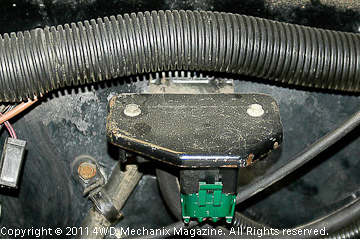 The MAP sensor mounts against the firewall and reads manifold pressure. At connector terminal B, with the ignition switch ON and engine not running, voltage should read 4-5 volts. This reading should drop 1.5-2.1 volts on a hot engine idling without a load in neutral or Park. Supply voltage from the ECU harness, read at terminal C of the MAP sensor, should be 5 volts plus-or-minus 0.5-volts with the ignition ON. If out of range on voltage readings, replace the MAP sensor.
 The throttle body has fewer parts than a carburetor and is easy to disassemble and rebuild. Little trouble occurs unless fuel is contaminated or air and fuel filtration is poor. Routine service is simply installing new OE-type filters. If there is a pressure regulator problem, the pressure regulator fits within the bowl beneath the fuel inlet. When servicing the pressure regulator, you check pressure at the test port. A running TBI engine will have 14-15 psi.NoteExcessively high pressure readings indicate a possible pinched fuel return line. Pressure regulator adjustments are usually minute and only to correct minor changes in the regulator and system over time. When there is not enough pressure, even after attempts to increase pressure at the regulators adjuster, there is either a restricted fuel supply system or a low output electric fuel pump in the fuel tank.
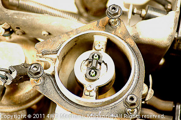 This is the fuel injector. Before removing the injector, check its spray pattern. If okay, leave the injector alone. To remove the injector, release its wiring leads and connector as an assembly. Grip the center collar of the injector with small channel lock pliers and rock the unit sideways; the injector pulls straight upward. A lock tab secures the base of the injector. Never attempt to twist the injector loose, which would damage the unit. Replace worn centering and O-type rings with fuel-rated new rings.
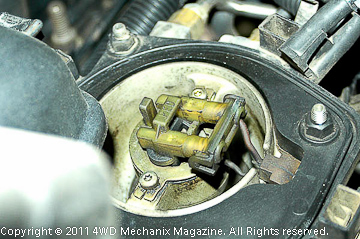 Years ago, I performed a good deal of work on TBI truck engines. A neat trick for testing injector performance is to hook your induction timing light to a spark plug lead. Run the engine with the light aimed at the injector and down the throttle body throat. A clean injector with normal pulse widths shows a uniform, conical fuel spray pattern. This is a quick check for poor flowing or clogged TBI injectors.NoteIf you cannot get a pattern at a given spark lead, try each of the four leads. A poor or absent fuel spray pattern is easy to discover this way. Be aware that a flooded engine will not flow fuel once the oxygen sensor signals the presence of raw, unburned fuel. Let the engine stand for a while before testing for fuel flow.
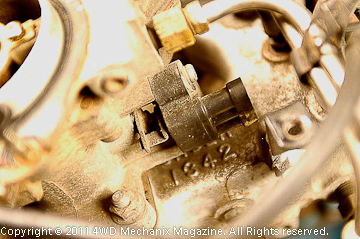 The throttle position sensor (TPS) sends the ECU constant data about the throttle opening and drivers demands. A correct TPS setting puts the output/input voltage ratio in the 0.925-0.935 range. This is calculated by dividing the input voltage to the TPS into the output voltage reading. Output voltage should be 93% of input voltage. For this test, the ISA plunger must retract away from the throttle arm. The throttle should be in its idle stop position (fully retracted).
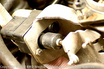 This is the Idle Speed Actuator (ISA) for the 2.5L TBI engine. A special exerciser tool is used to fully extend the ISA plunger. Fully extended, the plunger should bring an unloaded engine to 3500 rpm. This is a high rpm for a stationary engine, and I advise removal of the fan belt(s) for this brief test and adjustments. Before performing this test, the A/C should be off, the throttle body intake bonnet removed and the engine fully warmed. Use an accurate tachometer to pinpoint 3,500 (crankshaft) rpm.NoteDuring the 2.5L TBI era, the Ele. AB.99 tool was a Jeep dealership service device for exercising these ISA units. Make sure the plunger extends fully when performing this test. Set speed only with the ISA plunger fully extended. Do not run an unloaded engine at this speed for longsimply confirm the rpm.Testing and Calculating TPS Voltage
The voltage input for the TPS is typically in the 5-volt range. Output voltage to meet the idle-stop ratio of 0.93:1 or 93% is checked and adjusted with the ignition switch in the ON position and the 2.5L TBI engine not running:
1) Determine input voltage by first setting your voltmeter for 12-volt DC readings. At the TPS terminals A, B and C, insert the negative (-) lead into the backside of terminal B. Insert the positive (+) lead into the backside of the C terminal. You should get a reading around 5-volts. Use the hundredths of a volt scale.
2) Now move the positive (+) voltmeter lead to the A terminal. Read the output voltage.
3) Divide the input voltage reading into the output voltage. A figure of 0.925-0.935 should result. 0.930 is optimal for a TPS switch with the throttle against its stop position and the ISA plunger tip not contacting the throttle arm.
4) You can adjust the TPS switch carefully to obtain the correct output voltage. If the specification is not attainable, replace the switch.
NoteThe ISA motor can be retracted by use of a special exerciser tool. TPS voltage adjustments can be made using a special tester, the dealership recommended DRB-II® or DRB-III®. If you do not have these devices, the ISA motor is removable for this test; an accurate voltmeter test, as described above, provides a reasonable alternative. Reinstall the ISA motor in its original position after setting the TPS.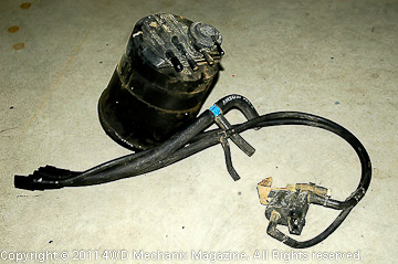 The EGR canister purge valve is a solenoid controlled by the ECU. The valve applies and shuts off vacuum to the EGR valve and the Evaporative Canister. The solenoid prevents the EGR and canister from operating during the engine warm-up mode, at an idle, during wide open throttle and during quick acceleration and deceleration. If you disconnect this solenoid, the EGR and evaporative canister will operate at all times, causing rough running and hazardous vapor conditions.
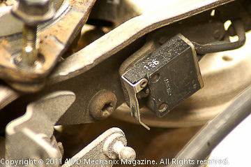 The wide-open throttle (WOT) switch should look familiar. A similar device was used on BBD carburetors. WOT switch activation will cause the ECU to ground the EGR/Evaporative Canister solenoid, cutting off vacuum to these devices to prevent their operation during full-throttle mode. Activation of the WOT switch also signals the ECU to ignore the oxygen sensor and allow the TBI injector to flow a pre-set amount of extra fuel.
 This is the oxygen (O2) sensor (at right) used with the 2.5L TBI engine. It is an electrically heated unit located at the base of the cast exhaust manifold near the header pipe. The benefit of a heated O2 sensor is quicker closed-loop functions during engine warm-up and stable performance during extended periods of idling. By reading the oxygen content in the exhaust, the O2 sensor provides the ECU with vital, continually changing information about the air-fuel ratio. The ECU adjusts fuel flow to provide optimal performance and low tailpipe emissions.
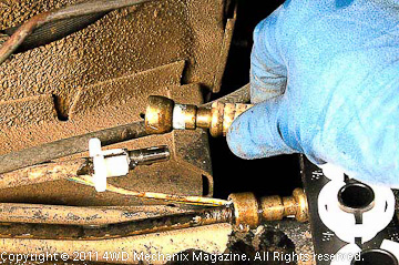 Do not attempt to disconnect fuel lines without these tools! Pipes will separate quickly and easily with the right tool. This is a Lisle product purchased at a Sears retail store. Various sizes fit fuel and common A/C couplers. Whether you are servicing the fuel filter, removing the engine or changing fuel lines, these spring release devices can prove essential. Coupler repair kits are available from Mopar/Jeep.
 The EGR valve has been popular since the mid-1970s. Exhaust gas recirculation under specific conditions will reduce oxides of nitrogen, the main cause of visible pollution. As a certified emissions mechanic, I learned the value of the EGR and some of its ancillary benefitsmainly its ability to lower the upper cylinder temperatures to below 2500-degrees F. The EGR is lifesaving for engines and valuable for the environment. Always make certain the EGR valve functions properly. You can test this valve with a vacuum hand pump.
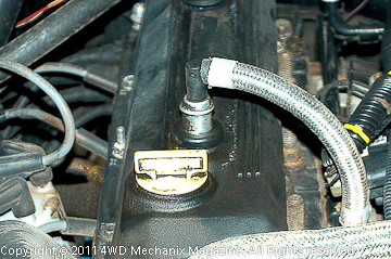 The positive crankcase ventilation valve (PCV) is a routine service item. This simple device helps purge the crankcase of toxic and damaging fumes. While part of a closed crankcase emissions system, the PCV valve does require replacement at normal intervals. If stuck open, the PCV will create a nuisance vacuum leak. If clogged or stuck closed, the PCV can allow excessive crankcase pressure and even create crankshaft seal or engine gasket leaks. I replace the PCV valve at 30,000 mile intervals.


